

When we replace one of the 10K resistors with a 3.3K resistor, the scaling factors become 3 and 1 and one third of one signal gets added to the second.īelow figure shows the resulting output waveform in pink, and the inputs in yellow and blue. The yellow and blue waveforms are the inputs, and the pink waveform is the output. A and B are both unity, since the two scaling resistors are the same. With the two 10K resistors, the output is simply the sum of the input signals. Of course, more than two signals can be combined together using this audio mixer. the resistor values relative to each other.įor example if one of the resistor values is 10K and the other is 5K, A and B become 2 and 1 respectively, since 10K is twice 5K.

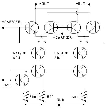
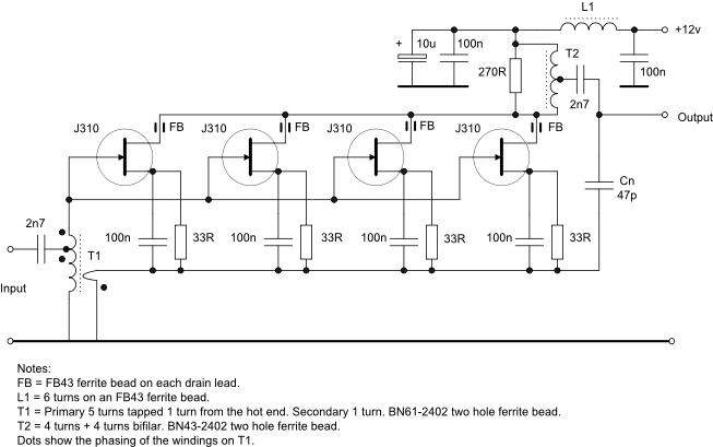
Where ‘z’ is the output signal, ‘x’ and ‘y’ are the input signal and ‘A’ and ‘B’ are the ratiometric scaling factors i.e. The beauty of this method is that a weighted sum is possible, depending on the individual resistor values. The resistors prevent the signal sources from interfering with each other, the addition happens at the common node, not at the signal sources themselves. The simplest additive mixer is simply two signal sources connected to two resistors in the following fashion: Like their name suggests, additive mixers simply add together the values of two signals at any instant, which results in a continuous waveform at the output that is the sum of the values of the individual waveforms. There are two types of Analog Audio Mixers - Additive Mixers and Multiplicative Mixers. Mixers find a lot of use in audio and RF systems and rarely used as simple analog ‘computers’. A mixer is a special type of electronic circuit that combines two signals (periodically repeating waveforms).


 0 kommentar(er)
